1 min read
A Cleaner Powertrain Design Driven by Stringent Emission Standards
When Toyota launched the first Prius in 1997, many consumers probably didn’t imagine that just 20 short years later the electric- and hybrid-vehicle...
3 min read
Eric Neleigh : Sep 19, 2018 7:30:00 PM
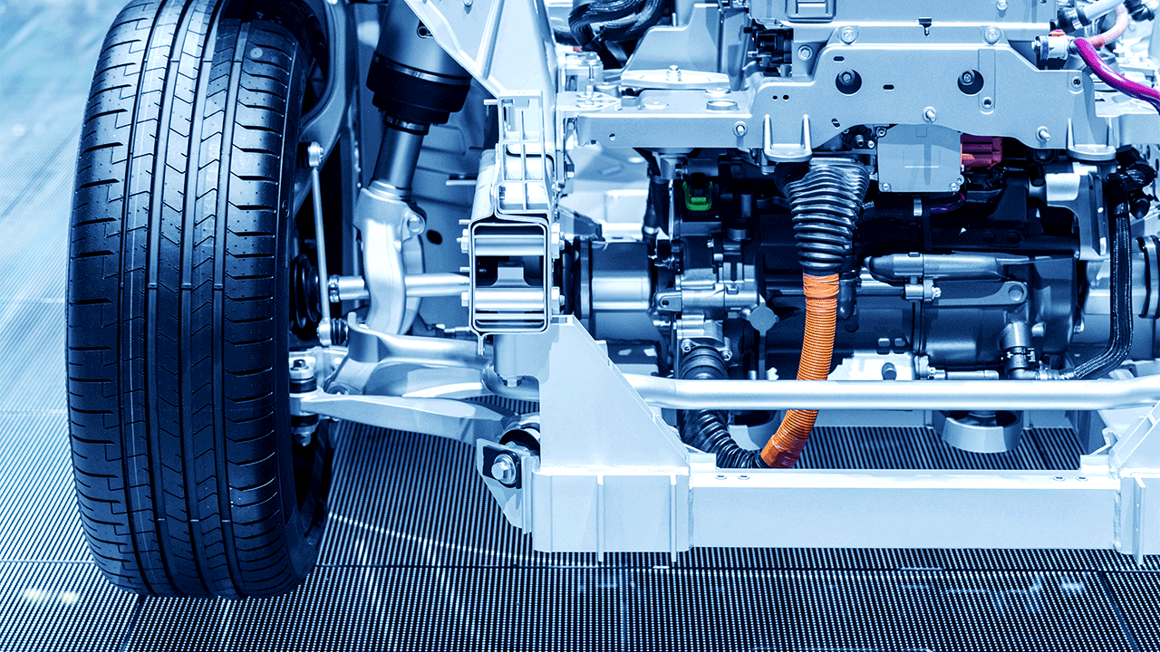
One of the most integral elements of the Hybrid and Electrical Vehicle or H/EV is the control technology. 
Due to these vehicles operating in a vast range of environments the motor will regularly switch through various loads. With that said, the most important issue is improving motor control efficiency while maintaining performance and avoiding damage. It’s wise to test control algorithms for motor control through simulation before applying power to any circuit. Especially when working with hundreds of volts and/or hundreds of amps of current. A simple mistake in your control algorithm can damage components or even worse cause collateral damage.
Before creating your simulation, consider how you are going to create or obtain models for your inverter and motor. Inverter models are usually less complex to create. High power switching transistors and diodes will have quite a few of their characteristics published in their manufacturer’s data sheet. These numbers can be plugged into the 3-phase inverter model VI in the LabVIEW Motor Simulation Toolkit.
Getting motor model parameters can be more difficult. If you are fortunate, the motor manufacturer can supply a JMAG-RT model (.rtt) or an ANSYS motor model file (it’s in a text format, so .txt). Otherwise, you have three options: 1) You can make a custom model from scratch compatible with the parameters needed by the NI toolkit, 2) Model your motor using the ANSYS software, or 3) Model your motor using the JMAG-RT software. Fortunately, you do have the option of signing up for the free JMAG Express Online access and generating your own .rtt file.
This still isn’t ideal because you need to know quite a few details about the construction of your motors such as magnet shape, slot dimensions, and wire characteristics to name a few.
With some form of parameters collected or models provided, these can be fed into the toolkit for different fidelity levels of models: constant parameter model/linear model, variable parameter model, and FEA model, with the fidelity increasing from constant parameter to FEA. Naturally, the number of resources required increases with fidelity. Examples of simulation for different types of motors are included in the toolkit, notably: AC induction motors, permanent magnet synchronous motors, or switched reluctance motors.
Here is an example of a PMSM finite element analysis model simulation with the following settings and start speed of 0 RPM.
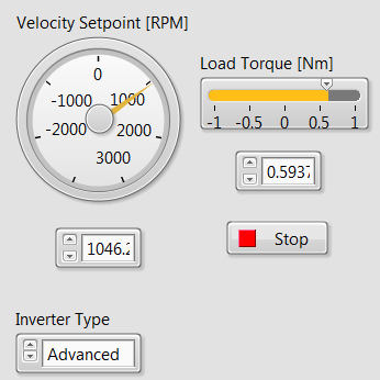
Here we can see the velocity ramp up to the setpoint over time: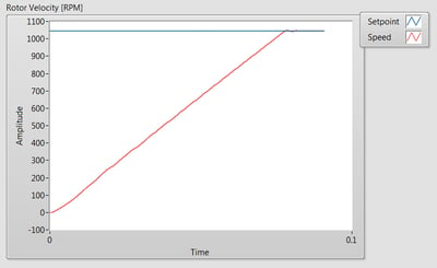
Under Acceleration, the current draw is quite large for the 3 phases. Note how much it drops when reaching the RPM setpoint: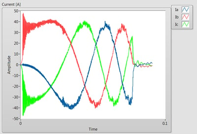
And how the electromagnetic torque settles to the load torque:
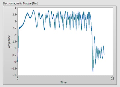
The initial conditions can be adjusted dynamically during the simulation to see what happens.
Instead of using a simulated inverter or trying to replicate an existing control algorithm in LabVIEW, you could input the digital control signals from an actual ECU to an FPGA simulation of the inverter and motor to see what happens while changing the inverter and motor parameters. You could also create your control algorithm in LabVIEW and output the digital signals to actual transistor gates on a real inverter to control a physical motor.
Though only a few of the simulation models were evaluated, there are various other simulation models offered through the highly accurate toolkit that will allow you to approach your motor simulation confidently. Whether you are armed with hard data from manufacturers or creating a model from scratch you can get your motor running and be on your way in no time. For a more complete investigation, the many LabVIEW examples that ship with the toolkit as well as the help file should aid you greatly in your understanding of motor simulation.
The Motor Simulation in LabVIEW was shown at the recent Electric and Hybrid Vehicle Technology Expo in Novi, MI.
If you missed the show, Contact Us and download the latest white paper to learn more about motor simulation and advanced testing needs.
[i] http://www.chicagotribune.com/classified/automotive/fuelefficient/sc-auto-cover-electric-vehicles-combustion-engines-20171018-story.html
[ii] IHS April 2016
Optimizing Propulsion System Performance with Integrated Powertrain Control Solutions
1 min read
When Toyota launched the first Prius in 1997, many consumers probably didn’t imagine that just 20 short years later the electric- and hybrid-vehicle...

Simulation and HIL Testing for Rapid Development Hardware-in-the-loop (HIL) testing is a necessary tool for any automotive manufacturer or supplier...

NI Drivven Powertrain Modules, Exclusively sold by LHPTS, an LHP division.